
![]()
 Carlson Civil is the civil engineering design software that puts you in the passing lane! What might take days with other civil engineering software takes just hours, or even minutes, with the powerful and intuitive Carlson Civil–it’s advanced technology that will work for you.
Carlson Civil 2020 with a focus on 3D imaging features. The new Carlson Civil 2020 release delivers the ability to apply textures, animation, surface updates, even record movies and import SketchUp objects.
In addition, the routines to draw profile and cross section sheets have many upgrades, and a notable, time-saving addition in both Civil and Hydrology is the ability to recall the toolbar status from previous versions so that users can quickly migrate their toolbar layout.
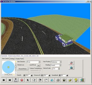
Work with Carlson Civil on AutoCAD (versions 2007 to current) or with the built-in IntelliCAD 9.0. With Carlson Civil, you’ll get true 3D, easy-to-use 3D, plus, with the updated 3D Flyover in Civil 2017, any surface edits made in CAD are automatically updated in the 3D view.
Road NET . Build all roads, intersections and cul-de-sacs in 2D and 3D with a single click of the “PROCESS” button.
Site NET . Elevate your estimating accuracy with this intuitive layer-based surface generator and earthwork calculator.
Lot NET. Quickly define an entire subdivision of lots based on an outer boundary, interior ROWs or Centerlines, and a simple set of user-defined “rules,” then pick “PROCESS” and the lots appear, defined and labeled.
Carlson Civil is one component of the Carlson Civil Suite and is designed especially for civil engineers and CAD technicians who need power and flexibility to make “short work” of even the most challenging design projects. At its foundation, Carlson Civil contains sophisticated and integrated command sets that are easy to learn, cost-effective and even fun to use!
Carlson Civil 2020 users have an extensive selection of analysis and design tools at their fingertips:
• Grid File Format – Added indexed binary grid format that uses 50% less file size and loads twice as fast.
• Triangulate and Contour – Added Reduce Meander filter for creating smoother contours.
• Triangulatiton File Utilities – Added function to break bent edges, to draw ridge/valley lines, to apply polynomial smoothing, and to export x,y,z text file of TIN points. Added controls for the color display method.
• Triangulation Surface Manager – Added method to draw Carlson points when adding points to TIN.
• Slope Zone Analysis – Added method to model surface using contours and hatch zones between contours.
• Contour Elevation Label – Added option for separate layers for main and intermediate labels.
• Design Pad Template – Added method to apply subgrade depth to pad when balancing.
• Edit Pad Template – Added functions to add and remove perimeter points.
• Cut/Fill Color Map – Added option to limit map cut/fill range to color. Added auto color styles.
• Cut/Fill Movement – New command to optimize earth movement with reporting by dozer and truck/shovel ranges.
• Draw Curb Ramp – New command to adjust 3D curb polylines to fit in ramp of specified dimensions.
• Lot File Manager – Added method in check lot to report closure with tolerance and option to draw symbol at any bad misclosures.
• Tag ROW Segments To Skip Frontage – New command to control setback amount for lot sides.
• Input/Edit Centerline – Added function to scale centerline.
• Station Equations – Added support for station-equations in more commands including Input-Edit Profile, Profile Report, Draw Sections, Input-Edit Sections and Section Report.
• International Roughness Index – New command to report this index of a profile.
• Draw Profile – Added option to use MLeader for leader labels. Added option to draw manhole names within an ellipse. For sewer profiles drawn as single lines, added setting for polyline width. Also for sewer profiles, added option to draw symbol for pipe flow arrow, option to prefix label layers with profile name, and option to skip rim and invert elevations for outlet and to skip invert-in label for first structure. For crossings, added option to label elevation at top of pipe and draw label leader to top of pipe. For the horizontal label box, added settings for text offset with a row and option whether to draw row header labels.
• Draw Section File – Added sheet output method to model space with viewports from layouts into model space. For crossings, added option to show pipe thickness. For crossings on-the-fly, added method to check selected .sew and .util files associated with the drawing. Added option to output each station to a separate dwg when using vertical stack. Added settings to control label position for grid elevation and offset labels.
• Profile Solids – New command to create profiles from solids or polymesh entities in the drawing.
• Section Solids – New command to create cross sections from solids or polymesh entities in the drawing.
• Input Edit Section Alignment – Added method to create sections at pipe crossings and method to use polylines to define cross section alignments.
• Section Cut Sheet – Added support for using grade ids.
• Design Template – Added method for subgrade depth to match existing surface for road rehabilitation. Added option for ditch on end of fill to use only when existing ground goes uphill from the tie.
• Template Grade Table – Added method to create table from polylines.
• Process Road Design – Added method to output TIN surface for bottom subgrade.
• Road Network – For point output, added controls for left and right sides.